Overview of the day:
We disassembled our robot and started sketching and designing how our Robosumo robot would look. I got working on the IR sensor and we decided to use a 9V battery in our robot.
Lab work:
Thankfully we had posted a good time in the Tip the can competition last week, so we didn’t need to do any more work on the robot or code for the Tip the can competition. This meant that we had lots of time to start brainstorming our ideas for the real Robosumo robot, as we needed a sturdier design that would hold up to multiple bouts.
We already decided that a laser-cut design would be the best option, as we can have whatever design we want, it is cheap as opposed to buying a pre-made kit online, and Adam is quite proficient in CAD programs like Solidworks so he would be good at designing it on the computer.
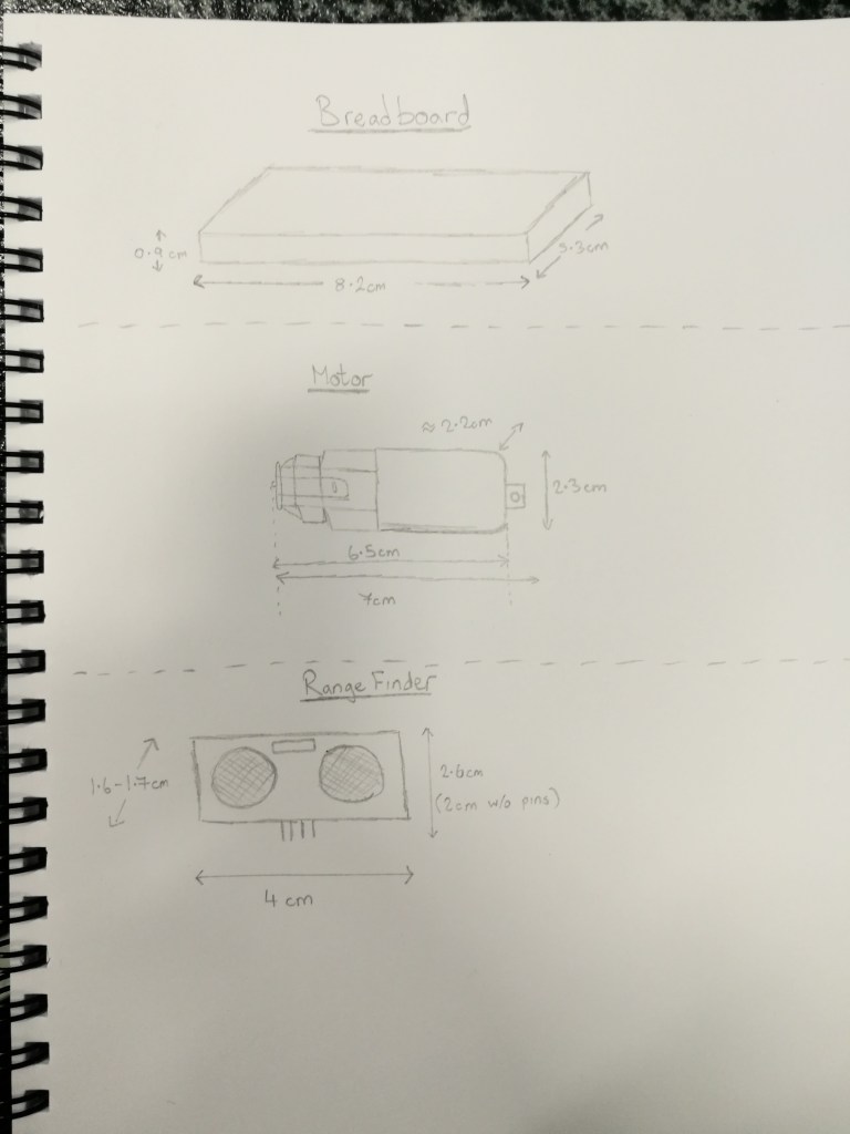
We started out our preliminary design process by taking measurements of every individual piece so we could start designing it, while keeping the maximum dimensions of 100mm in mind. Cillian sketched out these parts and their dimensions:
We toyed with having a ramped design on the front that would hopefully flip our opponents over, but decided that the ramp wouldn’t be able to be shallow enough while still being less than 100mm long. We thought that not having a ramp but having a low profile design could be tactically advantageous as we thought that on some robots where their rangefinder is mounted high up we would fly ‘under their radar’ and not be seen. We’ll see if this works out or not when we develop our designs.
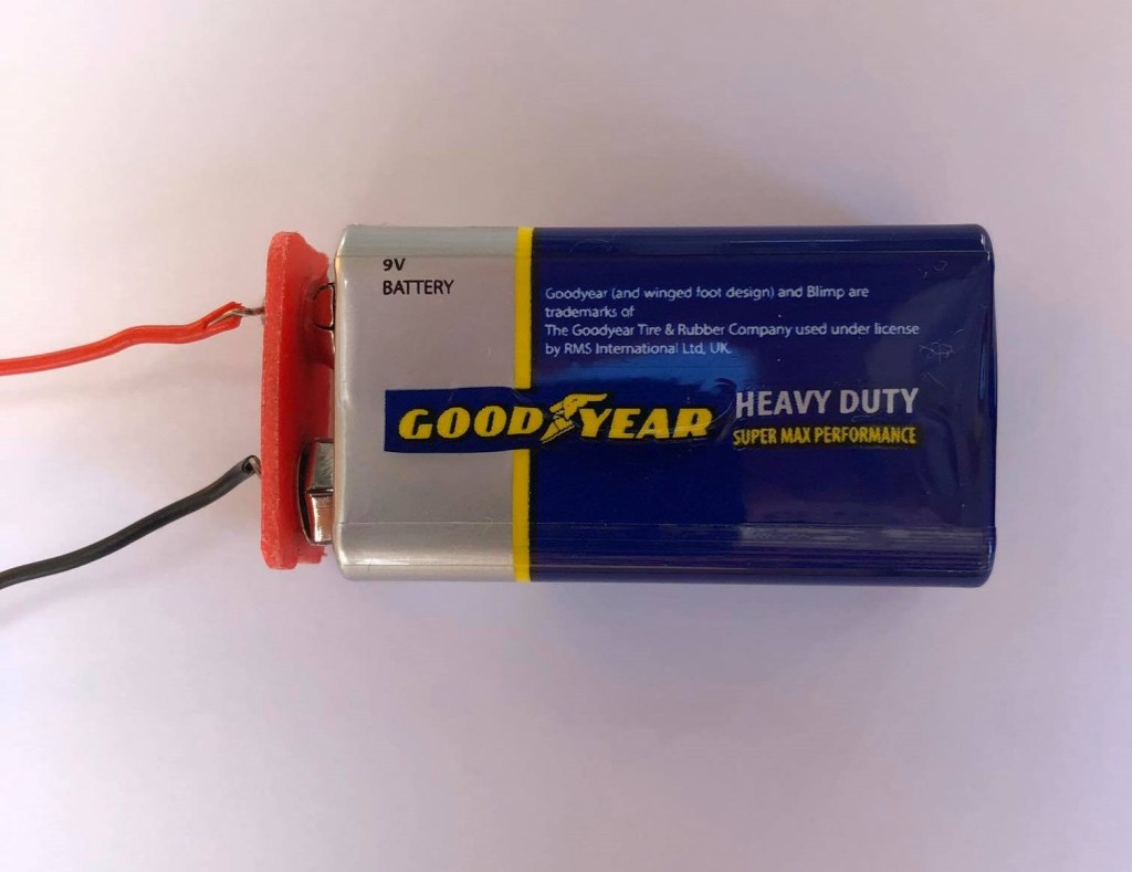
The battery pack that almost all teams are currently using are 6V. To make the robot faster, you need a higher voltage source which will spin the motors faster. We thought of using 2 of the battery packs in series to give us 12V, but we realised that would be too heavy. Instead, we’re going to use a 9V battery which will give us an advantage over most other robots that we’ll be fighting against, as ours will be slightly faster.
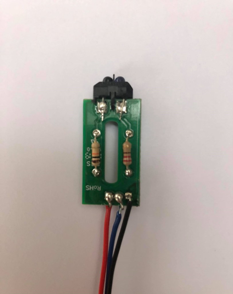
While Adam and Cillian continued with design ideas, I started soldering together the IR sensor that’s used to sense when your robot is almost out of bounds off the edge of the platform. I used pictures and diagrams from older articles on the cookbook website to try and solder together the sensor.
It uses 2 resistors and the IR sensor itself soldered onto a PCB board, with 3 wires soldered on to give power and send and receive signal.
What I learned:
I gained experience in the importance of teamwork and good communication skills while designing and brainstorming in a group setting. I learned how important diagrams and sketches are when communicating to others ideas in your head.
The challenges my team faced:
At early design stages there are always hurdles to overcome, because starting something from scratch is hard. I believe we made good progress though, and are in a good position to build on the designs we’ve done so far for next week.
Our tasks for next week:
For next week we are all going to sketch up some of our own design mock-ups for the robot, and discuss and compare them next week. We will then get into designing the robot in Inkscape, made up of separate panels of perspex which will be laser-cut and then hopefully slot into place. We will also have to find better wheels to use.
 Eric's RoboSumo blog