Week 7: Further designing

Overview of the day:

Further designing of robot and ordering new wheels. Deciding against using the IR sensor. First draft of final code for robot written.

Lab work:

Our objective for this week was to finalise a design and start drawing it in Solidworks. Adam has experience with this application and so he mainly did that side of things while Cillian and I sketched and brainstormed. Adam drew a number of parts in Solidworks but unfortunately cannot access them due to the college shutdown.

We decided against using the IR sensor as we thought it would be more hassle than its worth, hoping that our robot wouldn’t be pushed into the out of bounds area in the first place and if it was, the chances are it wouldn’t be able to drive itself back out as it would be being pushed out by the other robot anyway.
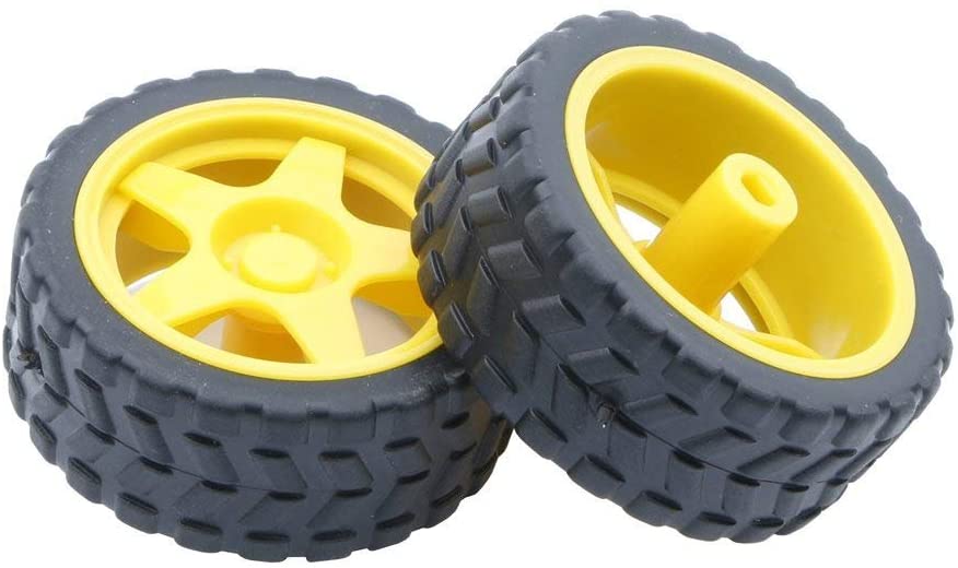
We have ordered bigger wheels off of Amazon because we think they will give us better traction and more dependability when bashing into other robots. We decided to go with these wheels as they are cheap and fit the shaft of our motors.

Cillian wrote code that would be used in the tournament, this code probably won’t be what we use on the day but it is a good base to work off of. The code can be seen here:

// Code used for RoboSumo Tournament
// Written by Cillian O'Brien
// Last Updated 11.03.2020

  #define button 4      // Switch button
  #define echoPin 5     // Trigger Pin for Sensor
  #define trigPin 6     // Echo Pin for Sensor

  long duration, distance;      // Defines variables for duration of pulse, and distance from object

void setup() {
  Serial.begin(9600);   // Sets baud rate for info from sensor [FOR TESTING]
  
  pinMode(trigPin, OUTPUT);   // Set up the trigger pin
  pinMode(echoPin, INPUT);    // Set up the echo pin
  
  pinMode(2, OUTPUT);         // Motor 1 Forward
  pinMode(3, OUTPUT);         // Motor 1 Backward
  pinMode(8, OUTPUT);         // Motor 2 Forward
  pinMode(9, OUTPUT);         // Motor 2 Backward

  pinMode(button, INPUT);     // Switch Voltage Check
}

void loop() {
  int push = digitalRead(button);      // Setting up var for reading when button is pushed

  digitalWrite(trigPin, LOW);
  delayMicroseconds(20);
  digitalWrite(trigPin, HIGH);  // Set trigPin high
  delayMicroseconds(20);        
  digitalWrite(trigPin, LOW);   // Send pulse for 20 us
  

  duration = pulseIn(echoPin, HIGH);  //pulseIn detects the duration of pulses from trigger
  distance = (duration/2)*0.034;  // Time to reach object * Speed of Sound in cm/us
  

  Serial.print(distance);   // This is to print the distance (in cm) of the rangefinder
  Serial.println(" cm");    // is detecting [FOR TESTING]

  if (button == 1) {
    Forward();
  }

  else if (distance < 10) {
    Forward();
  }
  
  else {
    Turn();
  }
}

void Turn(){
  digitalWrite(2, LOW);
  digitalWrite(3, HIGH);
  digitalWrite(8, HIGH);
  digitalWrite(9, LOW);
}

void Forward() {
  digitalWrite(2, LOW);
  digitalWrite(3, HIGH);
  digitalWrite(8, LOW);
  digitalWrite(9, HIGH);
}

Adam contacted Ted in relation to Inkscape and laser-cutting our designs.

What I learned:

This week we were only starting our final design of the robot, so we are still in early stages.

The challenges my team faced:

We were discussing whether the IR sensor would be helpful or not, but we ultimately decided against it after much deliberation. We believe that this is the right decision.

Our tasks for next week:

Next week Adam is continuing work on the Solidworks drawings, and hopefully Ted will reply to us and guide us through the process of laser-cutting the parts. Cillian will do some more refinement to the code and I will be working on more detailed designs and drawings of our robot.
Week 6: Planning and designing for Robosumo

Overview of the day:

We disassembled our robot and started sketching and designing how our Robosumo robot would look. I got working on the IR sensor and we decided to use a 9V battery in our robot.

Lab work:

Thankfully we had posted a good time in the Tip the can competition last week, so we didn’t need to do any more work on the robot or code for the Tip the can competition. This meant that we had lots of time to start brainstorming our ideas for the real Robosumo robot, as we needed a sturdier design that would hold up to multiple bouts.
We already decided that a laser-cut design would be the best option, as we can have whatever design we want, it is cheap as opposed to buying a pre-made kit online, and Adam is quite proficient in CAD programs like Solidworks so he would be good at designing it on the computer.
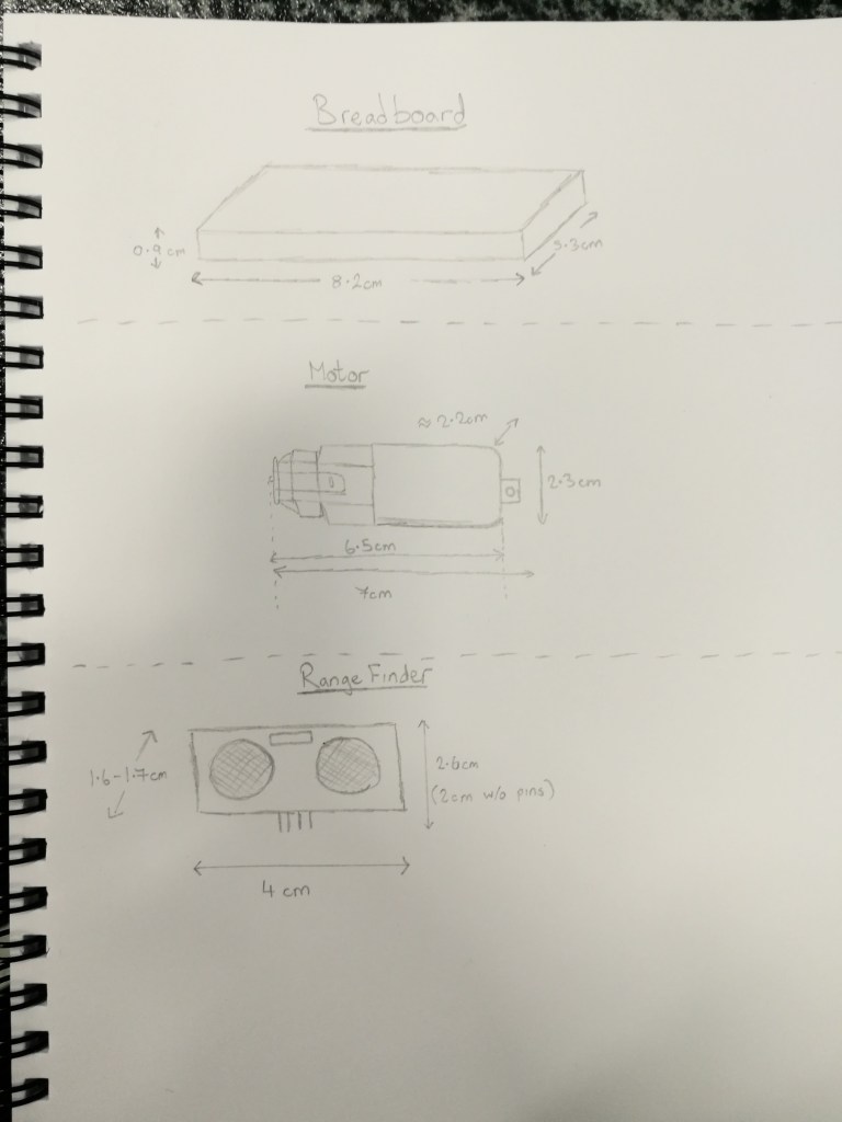
We started out our preliminary design process by taking measurements of every individual piece so we could start designing it, while keeping the maximum dimensions of 100mm in mind. Cillian sketched out these parts and their dimensions:

Cillian’s sketches of the main individual parts

We toyed with having a ramped design on the front that would hopefully flip our opponents over, but decided that the ramp wouldn’t be able to be shallow enough while still being less than 100mm long. We thought that not having a ramp but having a low profile design could be tactically advantageous as we thought that on some robots where their rangefinder is mounted high up we would fly ‘under their radar’ and not be seen. We’ll see if this works out or not when we develop our designs.

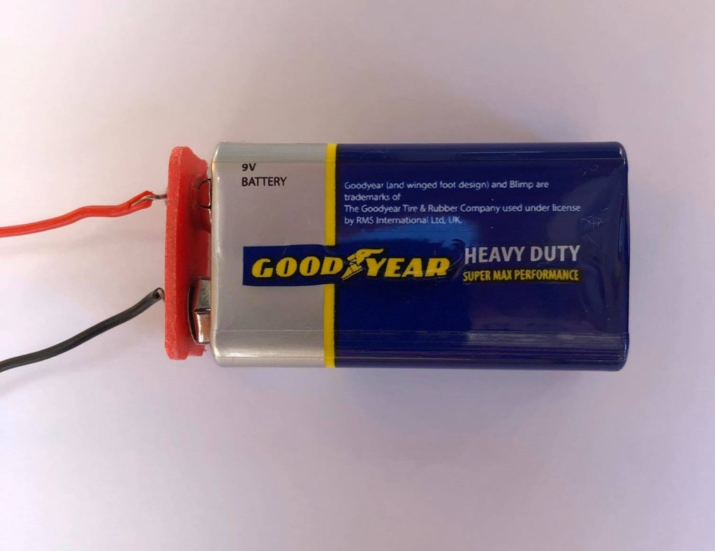
The battery pack that almost all teams are currently using are 6V. To make the robot faster, you need a higher voltage source which will spin the motors faster. We thought of using 2 of the battery packs in series to give us 12V, but we realised that would be too heavy. Instead, we’re going to use a 9V battery which will give us an advantage over most other robots that we’ll be fighting against, as ours will be slightly faster.

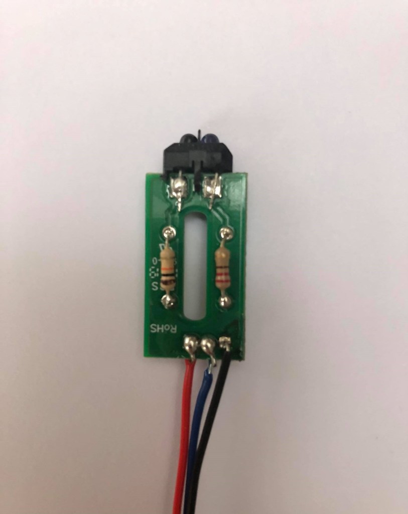
The finished IR sensor

While Adam and Cillian continued with design ideas, I started soldering together the IR sensor that’s used to sense when your robot is almost out of bounds off the edge of the platform. I used pictures and diagrams from older articles on the cookbook website to try and solder together the sensor.
It uses 2 resistors and the IR sensor itself soldered onto a PCB board, with 3 wires soldered on to give power and send and receive signal.

What I learned:

I gained experience in the importance of teamwork and good communication skills while designing and brainstorming in a group setting. I learned how important diagrams and sketches are when communicating to others ideas in your head.

The challenges my team faced:

At early design stages there are always hurdles to overcome, because starting something from scratch is hard. I believe we made good progress though, and are in a good position to build on the designs we’ve done so far for next week.

Our tasks for next week:

For next week we are all going to sketch up some of our own design mock-ups for the robot, and discuss and compare them next week. We will then get into designing the robot in Inkscape, made up of separate panels of perspex which will be laser-cut and then hopefully slot into place. We will also have to find better wheels to use.

Week 5: Building the robot and the Tip the Can competition

Overview of the day:

In the lecture Ted briefly went through the plan for the day and the room the competition would be taking place. We then had to assemble our robot and buy wheels for it last minute. We then competed in the competition.

Lab work:

We started off the lab with Adam showing the various wooden bases he cut out to me and Cillian. Our design for the tip the can competition was simple, but we agreed that for the Robosumo tournament we would laser cut our chassis.
Unfortunately Adam couldn’t find any suitable wheels in the model shop for the motors. This meant that we were in a big rush to find wheels so we could compete that day. Adam went to a Eurogiant shop and found a toy tractor that had wheels which fit the axles on the motors.
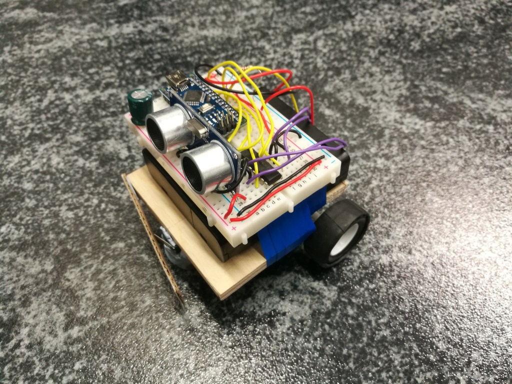
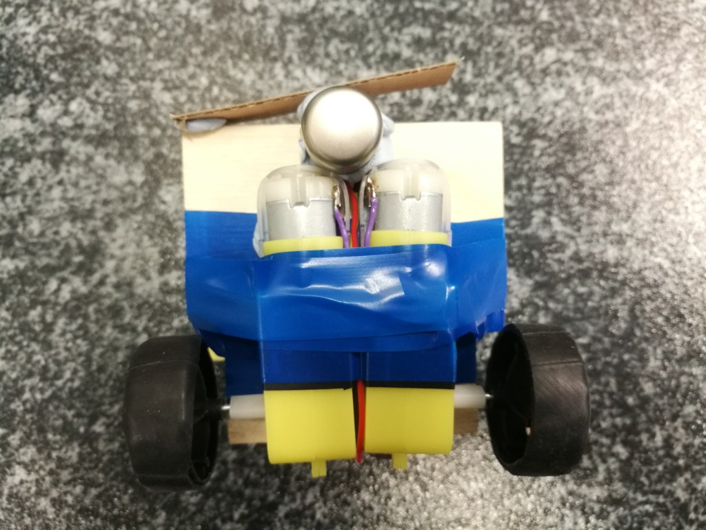
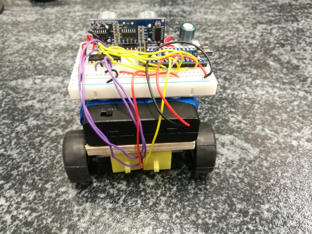
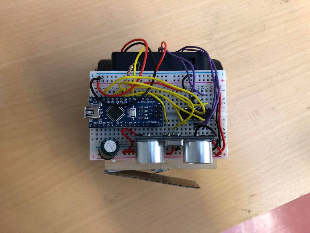
While he was doing that, Cillian and I worked on putting together the robot. We used the wooden piece as a platform which we attached everything onto. We taped the battery pack on top of the wooden platform, and blutacked the breadboard on top of that. We had the motors mounted underneath the wooden piece, held on surprisingly well with blu tack and electrical tape for added strength.
The wheels were rubbing against the platform so we cut out two notches out in the wood so the wheels weren’t restricted. We then mounted the switch in place with more blu tack, at the front of the robot. We later found out that the switch sometimes wouldn’t press, so we taped on a long cardboard piece that would give the switch a larger surface area where it could click.
At the front of our robot, I had the idea of using Cillian’s USB-key lid to act as like a dragging 3rd wheel that would keep the robot level and had a low friction surface that meant the robot tracked straight. This worked out well, and although our robot didn’t look the most technologically advanced, it posted a pretty fast time!

n

Our finished robot
The underside of the robot

n

The rear end
Plan view of the robot

n

When we assembled the robot we went into room 36 to post our first time. We realised that the robot didn’t have enough traction on the surface used for the competition, so Ted recommended that we use a bit of bicycle inner tube wrapped around the wheels to give them more traction.
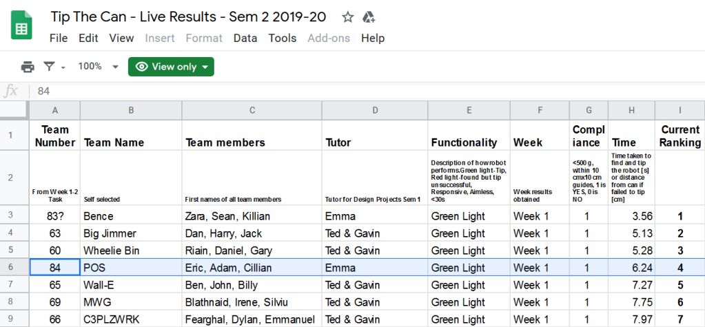
This worked out brilliantly and we posted a time of 6.24 seconds. This meant that we were in 4th place, which we were very happy with.

https://docs.google.com/spreadsheets/d/1Tojza0bPpKwD6aS6lRoePU9EUXQcxCEIINZDWM7AKm4/edit#gid=0

Unfortunately Adam’s phone which had the video of our robot competing broke, so we have no footage of it.

We decided that we wouldn’t be able to get a quicker time, so we started discussing our ideas for the Robosumo competition instead.

What I learned:

I learned how to work with others when building things, and how to better organise my time and allocate time slots for certain things. For example, we should’ve bought the wheels on another day and not have left it till the last minute.

The challenges my team faced:

We were in quite a rush to build the robot and go looking for suitable wheels for it, which was our fault for leaving it till the last minute. In future we will be better at making sure to get things done in a timely manner.

Our tasks for next week:

We must now start the design of our Robosumo robot. We are probably going to make it out of laser-cut panels, as our robot isn’t currently sturdy enough to battle another robot.

Week 4: Finishing touches to our code

Overview of the day:

During the lecture Ted went through the rangefinder code and setup as well as reiterating the size and weight requirements for the tip the can competition. Once we got to the lab Cillian finalised our code with help from me and Adam and I soldered wires to the switch. We discussed plans for the chassis in more detail.

Lecture:

Ted first went through the requirements for compliance and the basic structure for the competition next week. He then explained to us how to use the HC-SR04 rangefinder. Although we had already mostly figured it out, it helped us further understand how it works and how to write the code for it.
These diagrams that Ted drew up were really helpful in better understanding the rangefinder:

He then wrote some example code up on the projector, although this was not needed by us as we already had our code pretty much done for the rangefinder.

Lab work:

Soldered switch

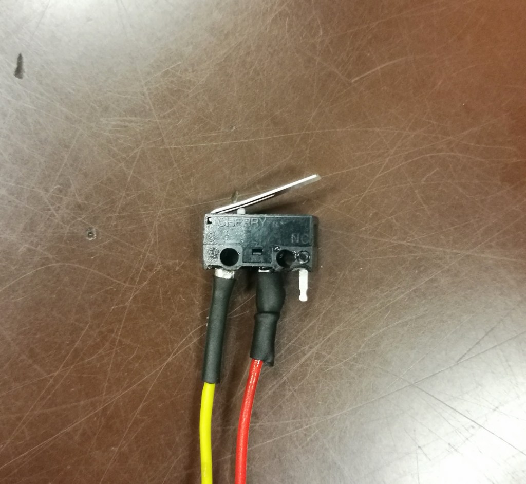
I started out in the lab by soldering wires to the momentary switch. I soldered a yellow wire to the ‘common’ pin as it would be connected to the digital output pin on the Arduino, and I soldered a red wire to the ‘normally open’ pin as that was going to 6V. I then covered the connections in heat shrink which would protect the wires from shorting out.

Then we all worked together to pretty much finalise our code for the tip the can competition next week. We ended up with this code:

// Code used for Tip the Can for RoboSumo
// Written by Cillian O'Brien
// Last Updated 26.02.2020

//////////////////////////////////////////////////////////////////////////
// [Notes for Before the Challenge]
// Adjust motor direction based on final build of chasis
// Change the distance [range] of sensor to the diameter of the arena
// Ensure to comment testing code
// Clean Up Code
//////////////////////////////////////////////////////////////////////////

  // Defining Pins rather than using ints, seems to solve a few issues that were happening 
  #define button 4      // Switch button
  #define echoPin 5     // Trigger Pin for Sensor
  #define trigPin 6     // Echo Pin for Sensor

  long duration, distance;      // Defines variables for duration of pulse, and distance from object
  
void setup() {
  Serial.begin(9600);   // Sets baud rate for info from sensor [FOR TESTING]
  pinMode(trigPin, OUTPUT);   // Set up the trigger pin
  pinMode(echoPin, INPUT);    // Set up the echo pin
  
  pinMode(2, OUTPUT); // Motor 1 Forward
  pinMode(3, OUTPUT); // Motor 1 Backward
  pinMode(8, OUTPUT); // Motor 2 Forward
  pinMode(9, OUTPUT); // Motor 2 Backward

  pinMode(button, INPUT);  // Switch Voltage Check
  
}

void loop() {
  
  int push = digitalRead(button);      // Setting up var for reading when button is pushed

  digitalWrite(trigPin, LOW);
  delayMicroseconds(20);
  digitalWrite(trigPin, HIGH);  // Set trigPin high
  delayMicroseconds(20);        
  digitalWrite(trigPin, LOW);   // Send pulse for 20 us
  

  duration = pulseIn(echoPin, HIGH);  //pulseIn detects the duration of pulses from trigger
  distance = (duration/2)*0.034;  // Time to reach object * Speed of Sound in cm/us
  

  Serial.print(distance);   // This is to print the distance (in cm) of the rangefinder
  Serial.println(" cm");    // is detecting [FOR TESTING]
  

  if (push == 1) {          // Button is Pressed [Hit the Can]

    digitalWrite(2, LOW);         // Keeps Going Forward for 1 Second
    digitalWrite(3, HIGH);        
    digitalWrite(8, LOW);
    digitalWrite(9, HIGH);
    delay(1000);
    
    digitalWrite(2, HIGH);        // Goes Backward for 2 Seconds
    digitalWrite(3, LOW);         
    digitalWrite(8, HIGH);        
    digitalWrite(9, LOW);
    delay(2000);

    digitalWrite(2, LOW);         // Stops for 60 Seconds
    digitalWrite(3, LOW);
    digitalWrite(8, LOW);
    digitalWrite(9, LOW);
    delay(60000);
    
  }
  
  else {                    // Button is Not Pressed [Hasn't Hit the Can]

    if (distance < 10) {
      // Object within Range
      digitalWrite(2, LOW);      // Goes Forward [Sees Can]
      digitalWrite(3, HIGH);
      digitalWrite(8, LOW);
      digitalWrite(9, HIGH);
    }
    else {
      // Object Out of Range
      digitalWrite(2, LOW);       // Turns [Default Mode]
      digitalWrite(3, HIGH);
      digitalWrite(8, HIGH);
      digitalWrite(9, LOW);
    }
  }

  delay(50); // Delay to allow ultrasonic reflections to die out
  

}

The idea for our code is to have the robot spin by turning the motors in the opposite directions, until the rangefinder reads the tin within range. Once it does, the motors spin in the same direction (forwards) until the switch is pressed. Once this happens, the motors continue to spin forwards for 1 second just to make sure the tin has registered our robot hitting it. It then reverses for 2 seconds and does nothing for 60 seconds, basically it is finished its code.

What I learned:

This week I got a better understanding of how the rangefinder works, and the code that goes with it. I also believe I improved my teamwork skills as the three of us were discussing what we will do next week at the competition.

The challenges my team faced:

This week ran quite smoothly. I had some trouble with the soldering joints not bonding initially, but eventually I got them to bond well and have good electrical connections.

Our tasks for next week:

For next week we need to further the detail of what our design will be for the competition. Adam is going to cut out different sized wooden pieces to make a base for the robot. He is also going to go to various model shops to see if they have suitable wheels for the motors.

Week 3: Momentary switch and rangefinder

Overview of the day:

We started off in the lecture with Ted explaining the SN754410NE driver chip in more detail. He then introduced us to the momentary switch that we would be using for the tip the can competition, showing us how to wire it up and connect it to the rest of the circuit. He also showed us some example code utilising the switch and motors. Once we got in the lab Cillian and I got to setting up the switch and motors, as well as beginning to figure out the rangefinder.

Lecture:

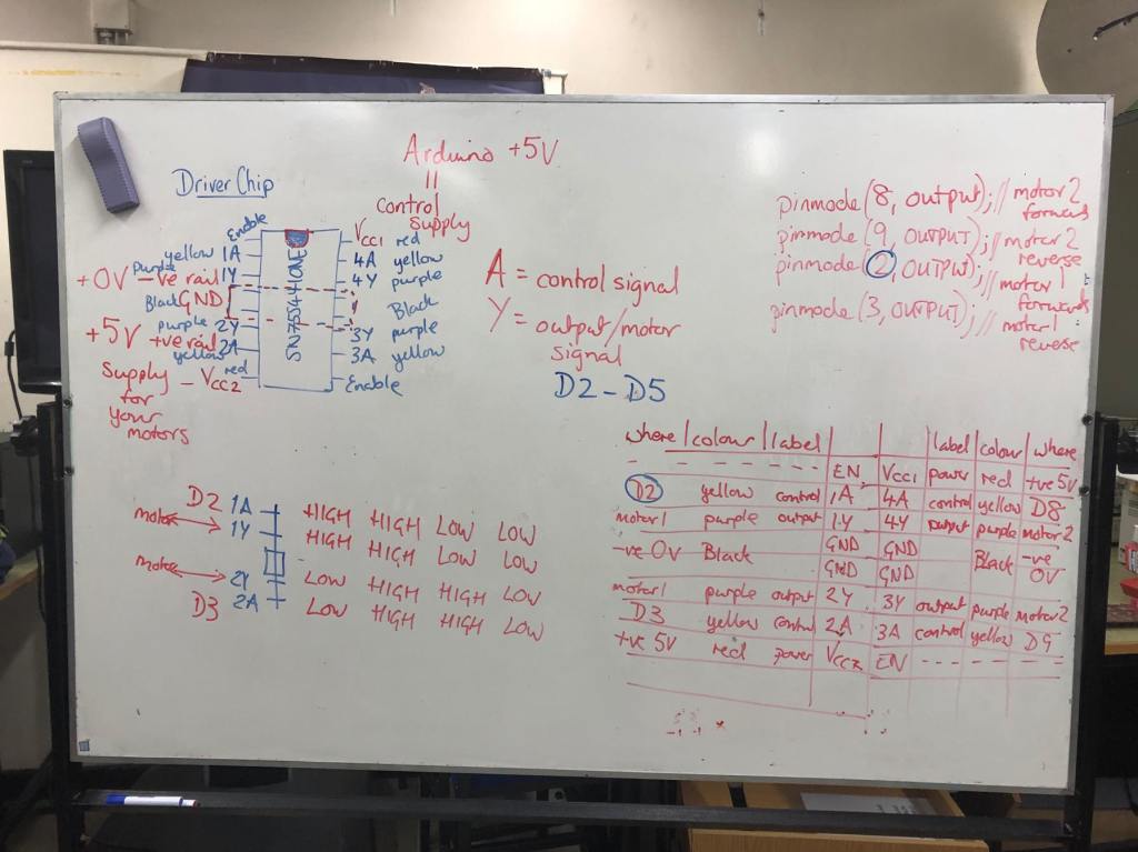
Ted began the lecture by explaining to us the driver chip in more detail, providing a diagram on the whiteboard. This wasn’t that necessary to us as we had got our motors up and running in conjunction with the chip, although it still furthered my understanding of the chip itself and the various outputs and inputs.

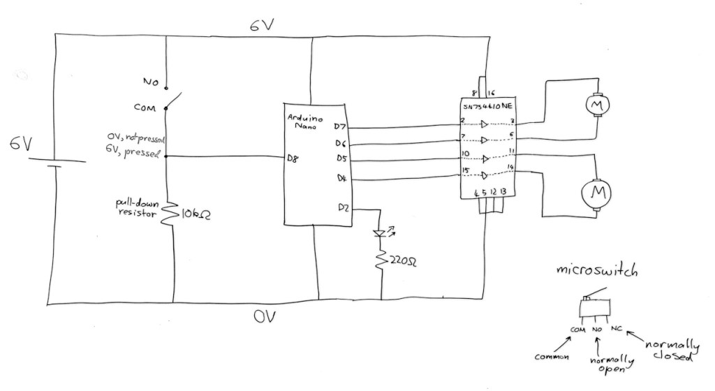
Ted then explained to us how the momentary switch will come into play. It will be used in our robots to activate once the robot has driven into the can, and will then send a signal to the Arduino which will tell the motors to reverse and so the robot will back up from the can. He explained each pin on the switch. The switch had 3 terminals: ‘common’ which went to ground and to a digital output pin on the Arduino, ‘normally open’ which went to positive and ‘normally closed’ which we wouldn’t be using in this instance. He showed in a diagram which can be seen above of how it connects to the circuit. One of the digital pins on the Arduino is connected to the ‘common’ pin as well as ground. The ‘normally open’ pin is connected to 6V, or positive.


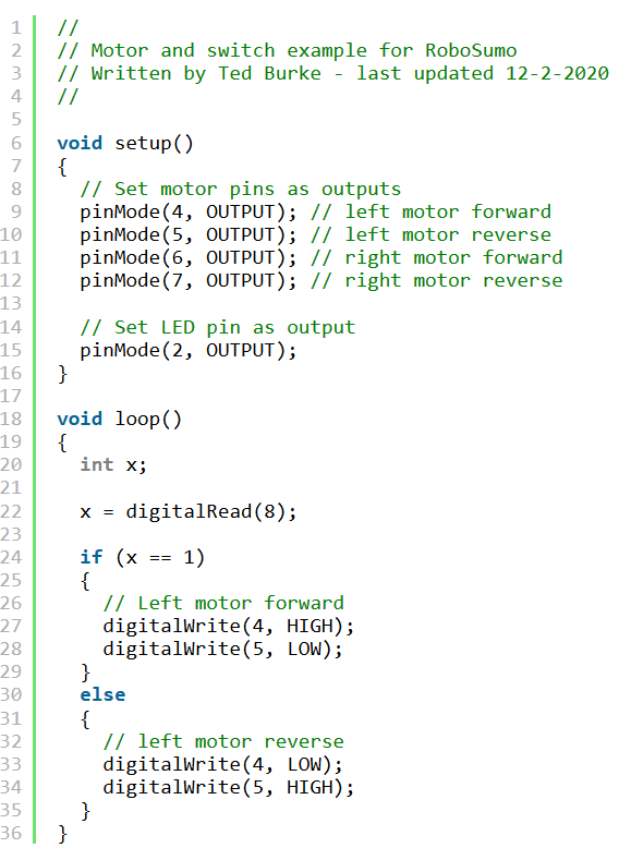
He then proceeded to walk us through an example code of the switch in use. In this example, when the switch is pressed it causes the left motor to reverse direction. The switch is assigned to pin 8 on the Arduino.
This was a good starting point that Cillian and I used when starting to work on the switch in the lab.

Lab Work:

Unfortunately Adam couldn’t make this week, but Cillian and I still got some good work done.
Firstly, we put the switch into our breadboard, wired it up as per Ted’s diagram and implemented Ted’s example code into our code for testing the motors. Cillian is the main coder in our team and so he wrote some code that would have the motors running, but when the switch was depressed they would run in the opposite direction. Here is a video of us testing the switch:

Me and Cillian testing out the switch

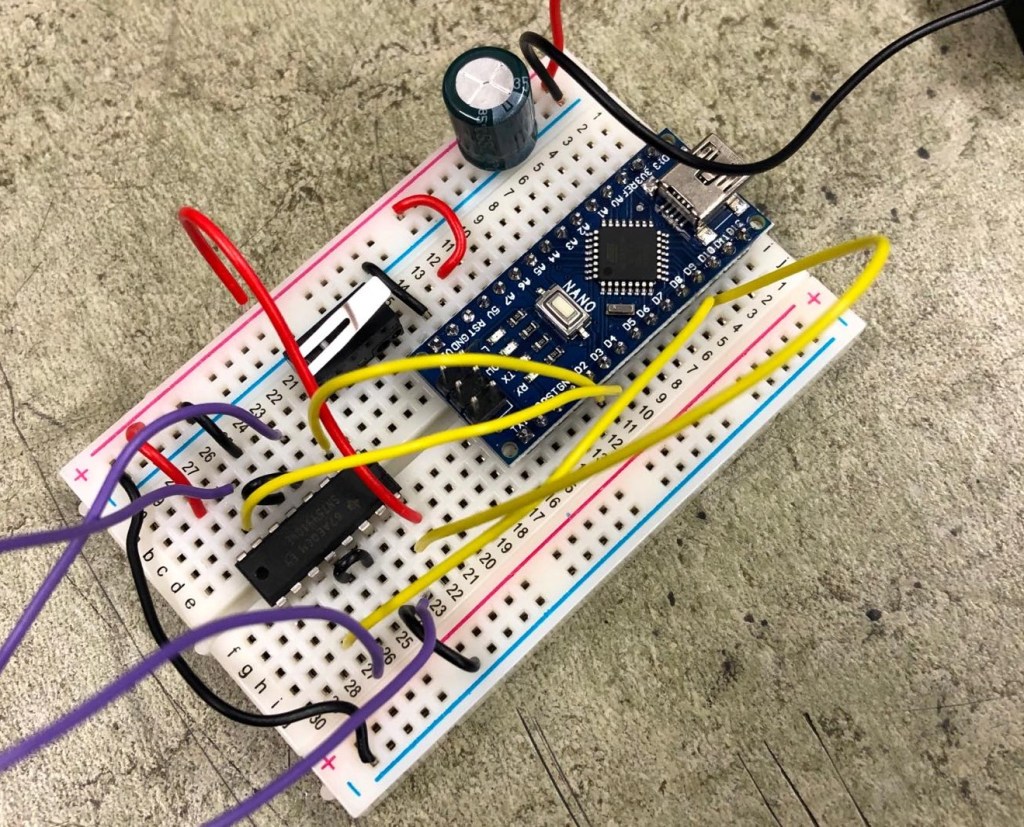
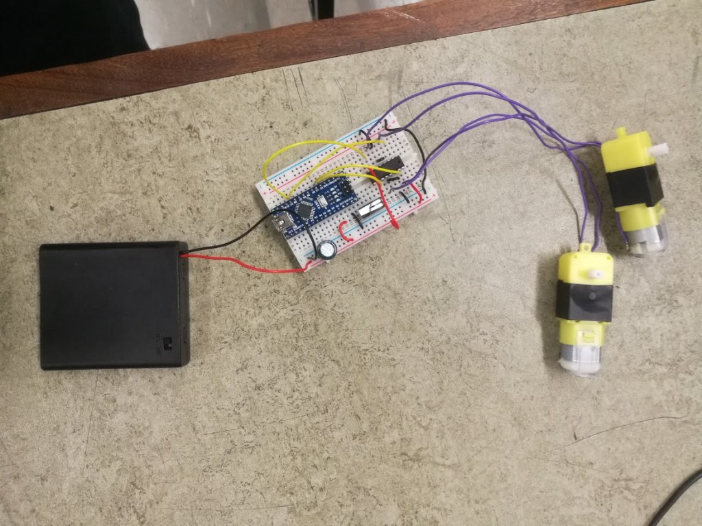
Here are some photos of our setup for testing out the switch:

Cillian and I didn’t run into any issues with the switch and we had plenty of time left, so we decided to try and work out how to use the HC-SR04 rangefinder. As Ted hadn’t gone through this during the lecture, we used older articles on the Robosumo cookbook to try and find example code of how to use it. We also asked Sean Moore in our class for some help as he had mostly figured it out already.

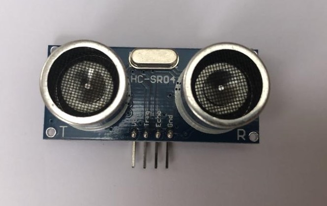
HC-SR04 Ultrasonic Rangefinder

The rangefinder works firstly by sending out an ultrasonic burst or pulse. It then waits for it to reflect off the surface back onto the receiver and times the delay between the two. This means it can be used to calculate the distance it is from other objects.

We will use this sensor to locate the can and then send a signal to the motors to drive forwards, hopefully directly into the can.
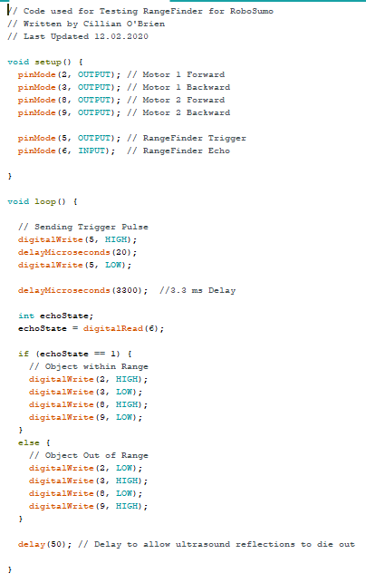
Cillian wrote out some code to test the rangefinder, which worked out great:

Here is a video of the rangefinder working, the code is set that when it is less than a certain distance from an object it reverses the spin of the motors.

What I learned:

This week I learned more about coding as Cillian explained to me each line of code for the rangefinder. I also learned how to use a basic momentary switch and what the different pins do.

The challenges my team faced:

Cillian and I struggled with the code for the rangefinder initially, but after looking through some example code and getting help from Sean Moore we eventually figured it out.

Our tasks for next week:

For next week we have to research more of what we’re going to use for the chassis. Cillian said that he will do some more work on the rangefinder, cleaning up the code and finalising it.

Week 2: Troubleshooting a broken Arduino, starting to develop the motors and starting my blog

Overview of the day:

Week 2 started off with a lecture from Ted about getting our WordPress blog up and running, giving us the rough module schedule, explaining the tip the can competition, teaching us of the importance of colour coding and finally introduced us to laser cutting and the application Inkscape. We then moved on to lab work where my team started to work on the motors and then tried to troubleshoot why they were working only intermittently.

Lecture:

For the duration of the RoboSumo module, we will be required to post weekly on a blog our progress and what we’re learning along the way. Ted introduced us to WordPress, which I have used once before in transition year, a website for creating your own personalised websites/blogs! He showed us how to sign up and pick a blog theme, and some tips for inputting videos and code into our blog posts. We were tasked with writing our first blog post of week 1.

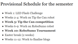
Ted then showed us the schedule for the module, which is as follows, (taken from the Robosumo Cookbook website):

Ted explained to us the tip the can competition, which is like a warm up competition in preparation for the real RoboSumo competition. The task is to have a robot that locates a stationary can, drives into it, registers it has driven into it and then reverse back a bit and stop. If this task was completed then a green light would come on on the can, and if not then a red light comes on. The basic restrictions of the robot are that it has to be a maximum of 100mm in each dimension and weigh under 500 grams. I look forward to seeing how our robot does, I believe my team are capable of getting a good time in the competition.

Ted then briefly ran through the importance of colour coding a circuit. Colour coding a circuit is essential to be able to easily see what wire goes where during troubleshooting, and is helpful to other people outside of your team who are not familiar with your circuit as they can easily identify where the wires go. Red wires are used for current flow that is always positive, black wires are used for current flow that is always negative, yellow wires are used for passing signals like between the arudino and a sensor for example and finally purple wires are used for the motors.

Ted then told us about how laser cutting our robot chassis is a viable option as you can create whatever design you want in the application Inkscape and the technical staff will cut it out of perspex. My team and I are considering going for this option, but we haven’t decided yet.

Lab Work:

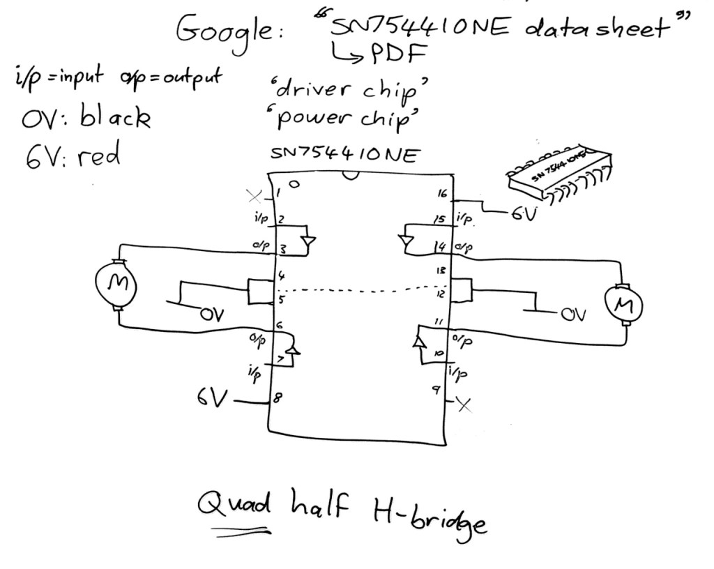
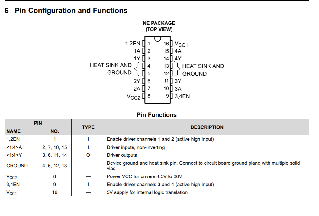
We started off lab work by trying to configure our Arduino to work with the SN754410NE driver chip. This driver chip is used to boost the power going to the motors so that they can turn faster. Without this, the motors spin incredibly slowly as the maximum output voltage of the Arduino Nano is only 5V. We used the driver chip’s data sheet to figure out how to connect the chip to the Arduino. Emma also explained to us the functions of each pin and drew a diagram of the chip, which proved very useful when hooking up the wires and motors to the breadboard and Arduino.

Emma’s chip pin diagram
SN754410NE data sheet

I had previous soldering experience as I have worked on some electrical components in the past. I built a quadcopter a few years ago for example, which required me to learn the basics of soldering. I also did some soldering in the Space Module part of the design projects module here in TUD. Therefore, I nominated myself to do the majority of the soldering work for this project. My first task was soldering wires to the motors. I made sure to pre-tin the stripped sections of each wire as well as pre-tin the copper connections on the motors. This meant that when I brought the wire and motor together and heated it with the iron, they would join together nicely without having to add too much solder as they already had solder on them. The solder joints seemed to be good and I was happy with them, although I believe I heated one for too long as part of the plastic on the motor melted somewhat. In the future I’ll know to be careful as to not overheat the delicate thin metal connectors on the motors. Adam helped me with the soldering by holding the wires in place, as otherwise it can be difficult to keep everything still, which is necessary as to not end up with a cold solder joint.
Once I had soldered the wires to the motors and wrapped electrical tape around them to give some mechanical strength, we tested the motors out with the code that Cillian was working on, with input from me and Adam.
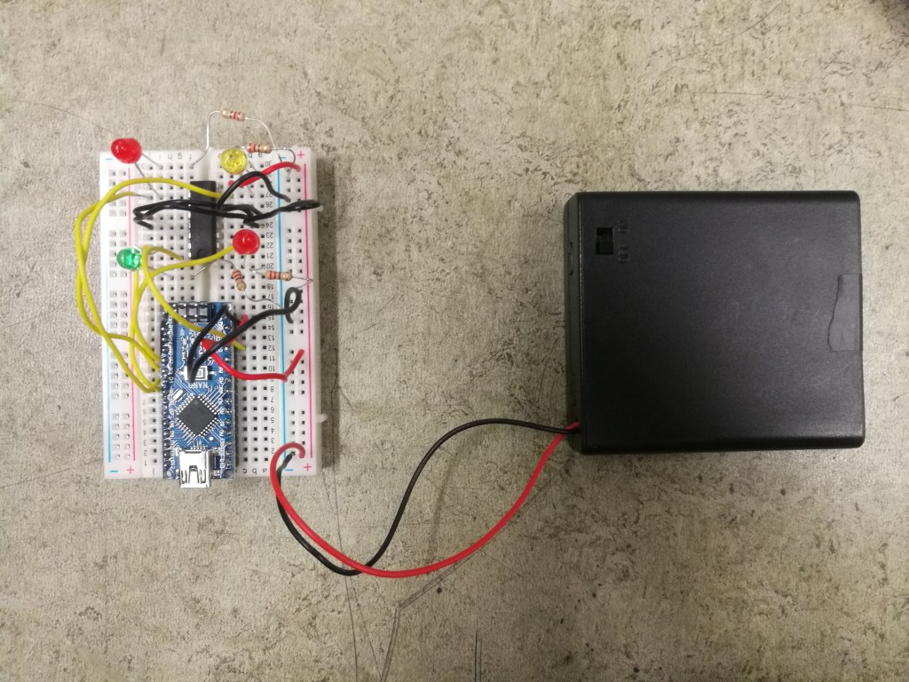
Unfortunately we were running into issues with how the code was running. The motors weren’t spinning in the way that they should have. They were intermittently starting and stopping in an unpredictable way. At first I thought that it was maybe a bad solder joint, but we tested different motors and they seemed to be doing the same thing too. Emma suggested that we replace the motors and some of the wire paths with LEDs so we could better troubleshoot the problem. It showed that the problem wasn’t with the motors as it persisted.

Troubleshooting with LEDs in place of motors and wires

With Emma and Cillian scrutinizing the code they were sure that nothing was wrong there, so we double checked all of our wiring and swapped out the driver chip to see if that was the issue. The problem didn’t go away, so eventually we swapped out the Arduino itself, loaded the code onto the new board and hooked everything back up.
Thankfully the motors now spun as per the code. We were glad that everything was in working order and were finished with the Arduino for the day. Next, we signed up to WordPress and started on our first blog post.

What I learned:

This week I learned mainly about the steps involved in troubleshooting, trying to go thorough it methodically and logically, isolating one part each time and eventually figuring out what part is broken. I also brushed up on my soldering skills, as I feel like each solder joint I did improved on the last. I had also never soldered components that delicate and so learned how important being careful with the heat time is.

The challenges my team faced:

This week we of course were challenged when trying to fix the intermittent issues with the motors spinning strangely, but eventually overcame this and isolated the broken Arduino board and replaced it.

Our tasks for next week:

For next week we need to start thinking about ideas for our robot chassis for tip the can, and start researching any parts we might need to purchase.

Week 1: Module introduction and intro to coding

Overview of the day:

Week 1 started off in room 8 where Ted introduced us to the competition of RoboSumo, where 2 automated robots are placed in a ring and have to push each other out of a designated boundary. What we will be doing isn’t up to as high of a standard as the examples he showed, but the general objective is the same. Ted introduced us to the Arduino nano computer and set us the initial task of making an LED flash in a simple circuit, as well as coding 2 LEDs to display our team number in binary. We then moved to the lab and conducted the experiments.

Lab work:

When we arrived at the lab we were first assigned into groups (my group members are Adam Byrne and Cillian O’Brien) and then we had to set up an LED in a circuit and write code on the Arduino program that would make the LED flash. Here is a video of the LED running our code which had the LED turn on for 1 second, off for another second and repeat.

Adam’s video of the LED turning on and off

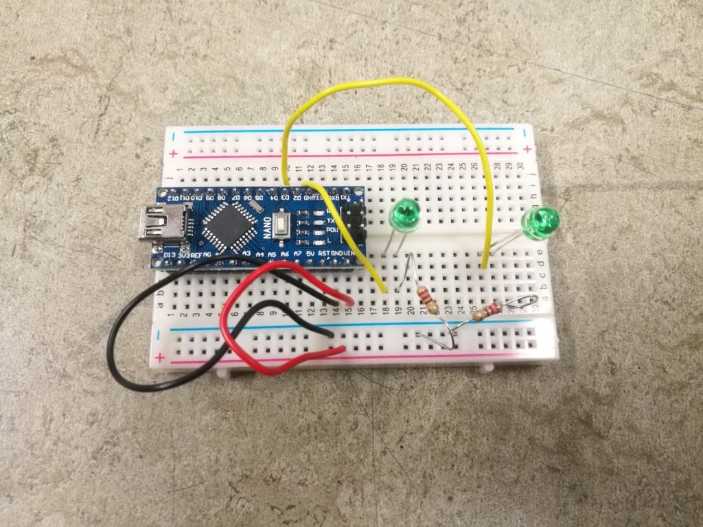
Once this was completed we moved onto the real meat and potatoes, which was getting 2 LEDs to flash our team number in binary. There were 3 steps to this. Firstly we had to figure out what our team number actually was in binary. Adam and I were new to this, whereas Cillian had some experience so he helped explain it to us as well as our lecturer Emma Robinson. I found it a tricky concept to grasp but by the end of it I think I had a good idea of how to convert from decimal to binary and vice versa. Then we assembled the circuit, adding a second LED and resistor to our previous one, assigning the diodes to the correct pins on the Arduino.

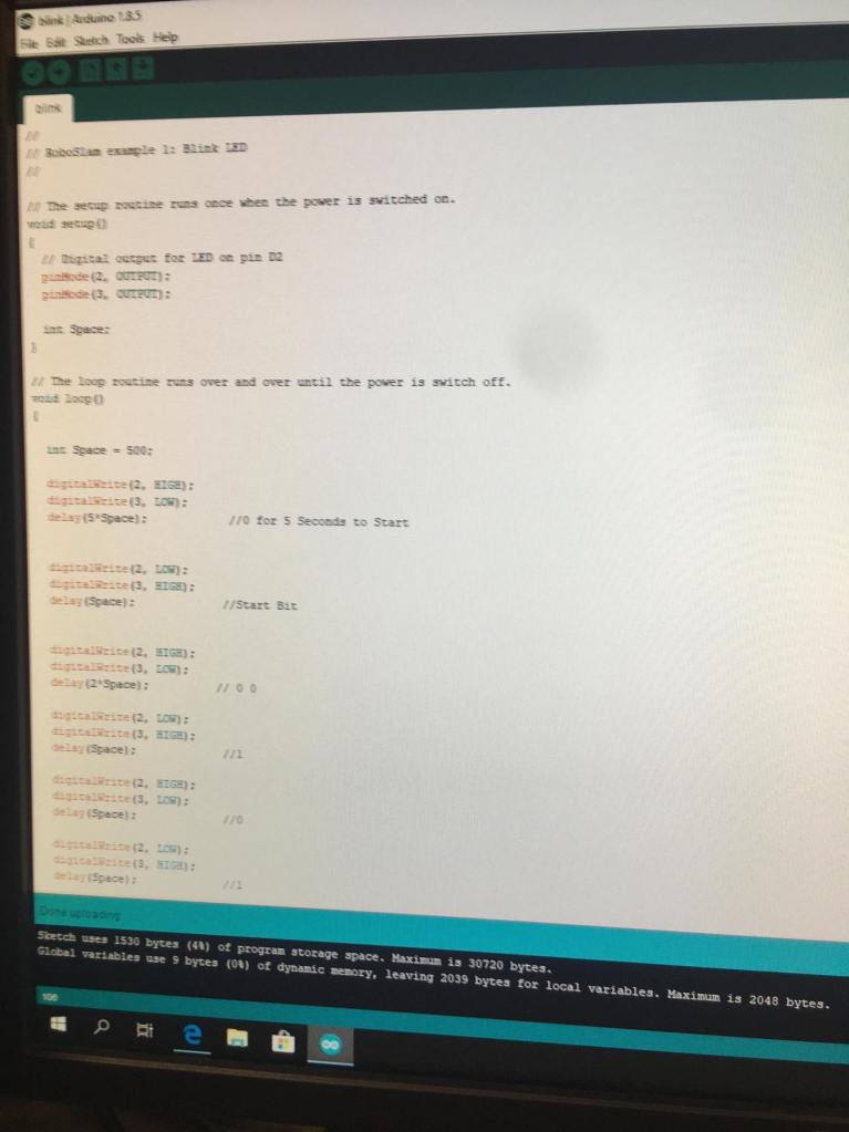
Once we knew the number in binary we set out coding the sequence on the Arduino. Again, Cillian had experience with this so he showed me and Adam the ropes. How it worked was we had a block of code for each flash of one of the LEDs. The code would tell one of the LEDs to receive current, sustain that for 500ms and then turn off. One LED represented 0 and the other 1.

Emma gave us a good tip to try and find patterns so we could repeat certain parts of the code where there was repetition, meaning that the code would be easier to read and also not be as long. I’m sure this method of working smarter, not harder, will help us when we start working on our project.

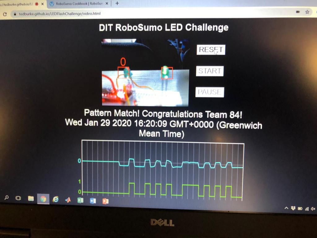
Once we had what we thought was the right code, we placed our circuit in front of the webcam that was recording on Ted’s binary reading website. We then ran the Arduino and pressed start on the website.

Passing the binary test!

Fortunately, our code was a success and the website correctly read our team number (84).

Success!

What I learned:

I learned various things this first week. I learned about the basics of Arduino, and how to code it and set inputs and outputs. I learned about the importance of colour coding wires on a breadboard circuit, as being easy to troubleshoot is a key aspect when designing and making circuits. I also learned how to convert a number from decimal form to binary, and the use cases of it.

The challenges my team faced:

One thing I found hard was grasping binary and how to convert from one number system to another, although I think that by the end I had a good, basic understanding of it.

Our tasks for next week:

Being the first week, we haven’t got working on our robot yet and so we don’t have many tasks for next week, apart from writing this blog post of course. Next week we’ll be getting into the swing of things.

Design a site like this with WordPress.com
Get started